kougs
kougs
So this is from another forum, owner is Ethan and this is his New and Improved and Cheaper Phoam Phraxionator. Most of what I'm to post is cut and paste from his postings. I will add some of my pics from my construction just for clarification. FYI, I did not use the 2” uniseal.
So, I got to thinking one day about how when the water gets down to the bottom of the original Phoam Phraxionator Tower, at 1500 gph, it ends up being less about water crashing down through the media, and more like the water sliding down the media. At this point, I believe that the Docs are likely beginning to settle back into the water column, rather than being drawn out to be a “bubble” to be removed from the system.
I talked with a few friends, asking them “where do the bubbles and phoam begin to form in your pond when you have an issue?” The answer, of course is the waterfall. If you have a waterfall, just the crashing down of the water into the water creates enough disturbance that the bubbles form, and the foam begins. Then, I thought, “why in the world do I even NEED a media for this unit?”
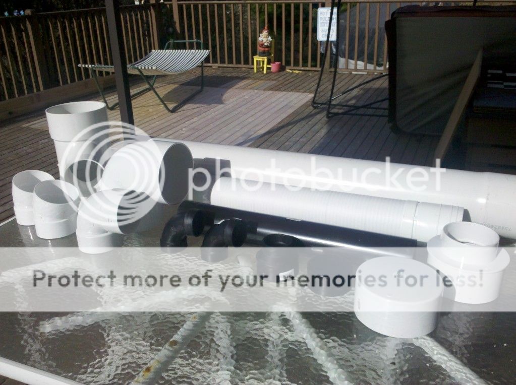
SO, the testing began. I built the first one, tested it, and dried it out and sent it yesterday to Flounder. I purchased some cheap supplies:
(1) 6” schedule 35 elbow
(1) 6” schedule 35 Tee (had to use a wye as there were no Tees)
(1) 6” to 4” reducer schedule 35
(1) 3’ Length of 6” schedule 35 pipe
(1) 2 feet of sdr 35 4” pvc
(2) 22.5 degree elbows
(1) 6” PVC schedule 40 CAP
(1) 3” schedule 40 PVC cap
(1) 3” to 2” reducer
(1) 2” 90 degree elbow
(1) 2” uniseal
You will need less than a foot of 3” and 2” PVC, schedule 40, and of course primer and glue. You will also need a jigsaw.
Here’s what you do:
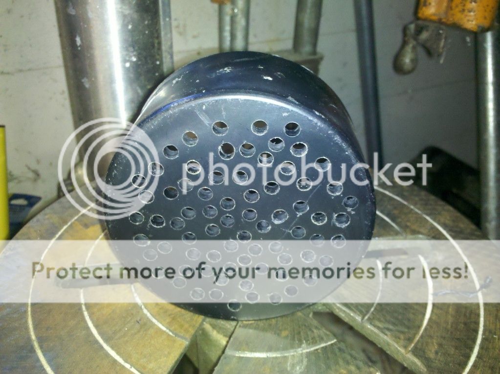
Step one:
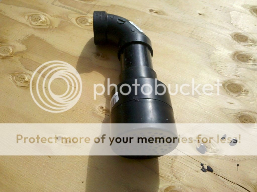
Drill using a 1/5” drill bit, around 25 holes in the 3” cap. This will be your spraybar. Attach to the 3” to 2” reducer using a short stump of 3” schedule 40 pipe, around 5-6” worth. Attach the two inch end of the reducer to a 4” piece of 2” schedule 40 PVC. Attach this to your 2” 90 degree elbow.
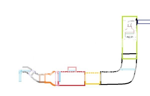
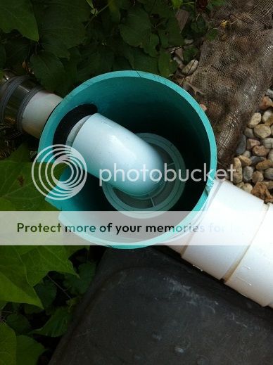
Step two: LIME GREEN
Take a 20” piece of schedule 35 pvc and drill a 3” hole in it for the two inch uniseal. This hold needs to be around 3” from one end. Make sure it is a clean hole, but know that there won’t be any pressure, as the uniseal is just to get the spraybar in place.
My Photo
Here's a detail of step 1:
My Photo
Step Three: Black
Glue the opposite end of the 20” piece of PVC into the 6” SDR 35 elbow. Make sure that the hole is at the top, not glued into the elbow, and is facing “away” from the elbow like in the example (Green vertical pipe)
Step Four: Yellowish Orange
Next, glue in a short 10” piece of 6” schedule 35 PVC into the other end of the 6” elbow.
Step Five : RED
Attach the 6x6x6 tee (6x6x4 preferable) to the elbow now. Make sure that the tower is pointing up and the T is on its back pointing up.
Step Six: BLUE
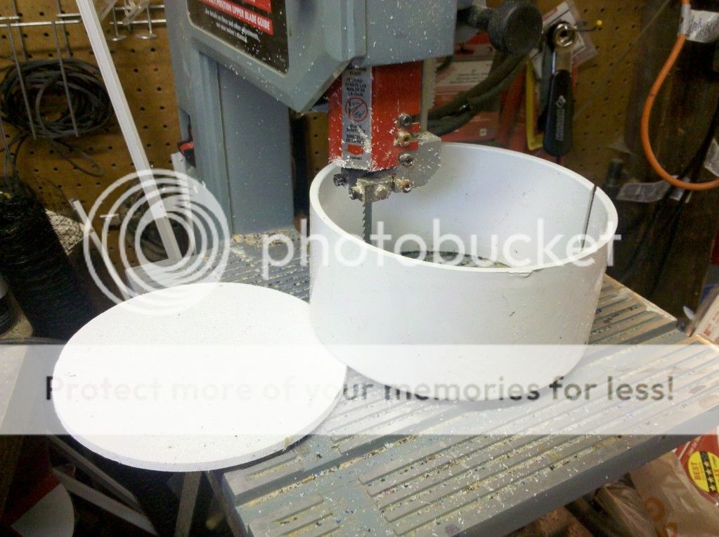
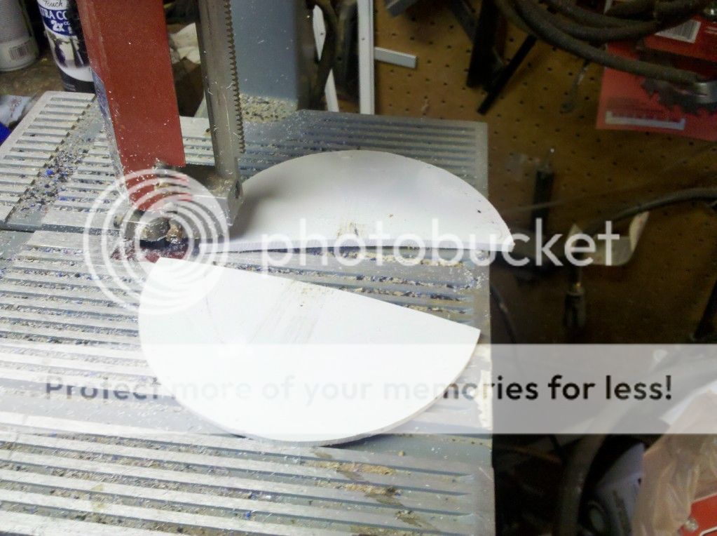
This is the hardest part of the unit. You have to cut a piece of PVC into a “moon” to fit between the Tee and the outlet. This prevents major BUBBLE LOSS. It encourages the bubbles to rise up, bringing the Docs with them.
I took a 6” Cap, drilled a tiny hole in the top of it and used a jigsaw to cut the piece out of the cap, as it happened to be the exact size I needed to do this. I glued that into the fitting of the tee, and
My Photo
Step 7: PINK
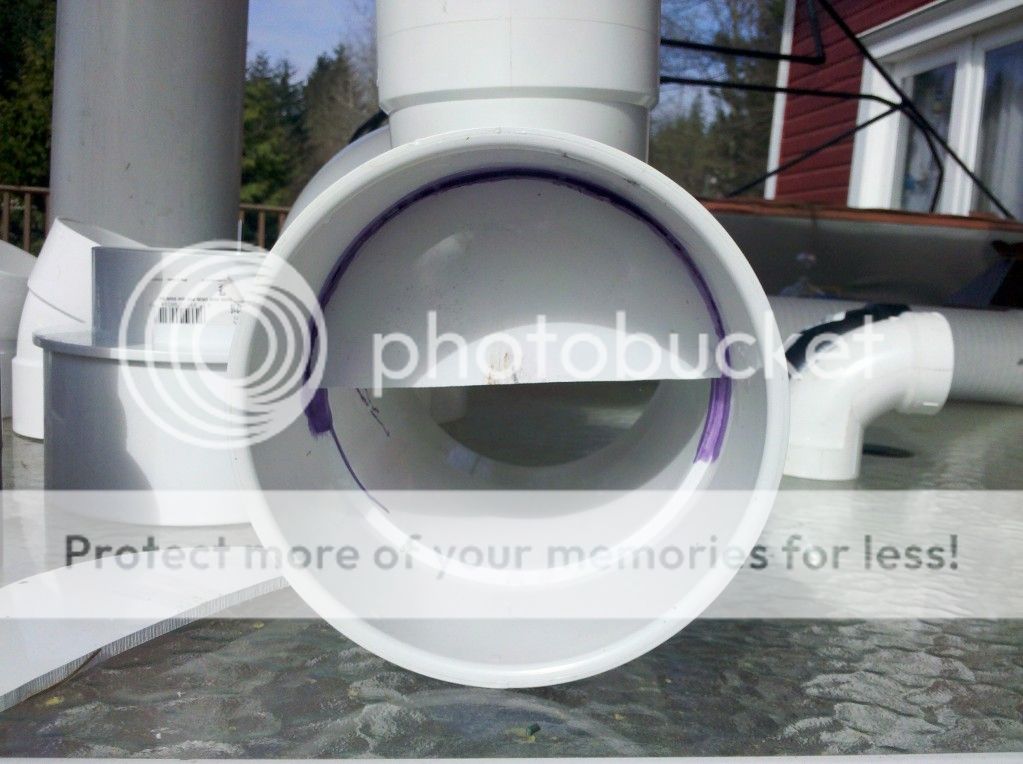
SMOOSH the 8” piece of 6” Schedule 35 pvc into it. This makes your “Phoam Phraxionator Phrontal Phoam Phixer Phit tightly”. It fixes the foam to go upwards, and out.
Step 8: Orange
Next, attach the 6” to 4” schedule 35 reducer to the end of that pipe.
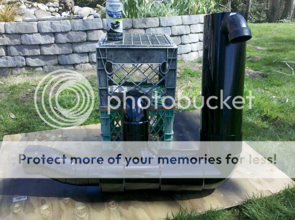
Step 9: Grey
Attach a short piece of 4” schedule 35 PVC (BROWN) into the 4” end of the reducer, maybe 6 inches worth, and attach a 22.5” 4” elbow to the end of the that pipe, facing upwards as shown in grey. Add a small 5-6” piece of 4” schedule 35 PVC to attach the next 4” 22.5 degree elbow. Shown in gray, add the next elbow, facing down, to get the water back into a completely horizontal position.
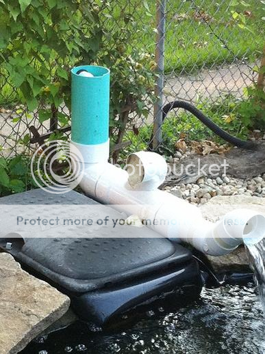
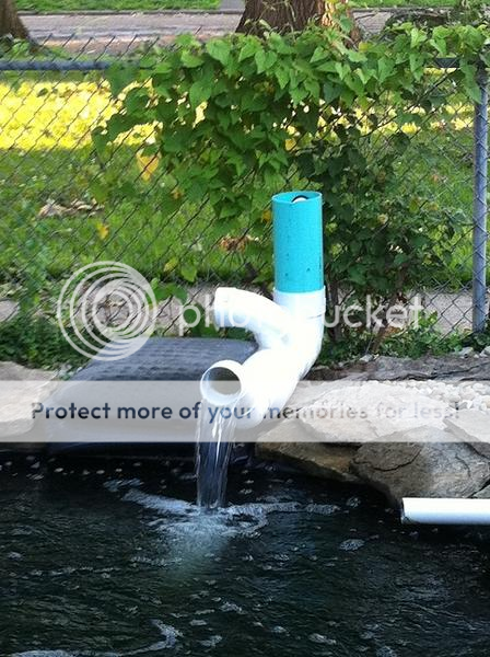
Step 10:
Add the spraybar by inserting the uniseal into the tower, shoving a one foot piece 2” PVC into it, showing around 1.5” of PVC into the tower. Attach the spray element to it with PVC Glue. Now you have a 2” input to pump around 1500-1800 GPH through the thing (there will be some back-pressure on the pump).
It works well.
My Photo
So, I got to thinking one day about how when the water gets down to the bottom of the original Phoam Phraxionator Tower, at 1500 gph, it ends up being less about water crashing down through the media, and more like the water sliding down the media. At this point, I believe that the Docs are likely beginning to settle back into the water column, rather than being drawn out to be a “bubble” to be removed from the system.
I talked with a few friends, asking them “where do the bubbles and phoam begin to form in your pond when you have an issue?” The answer, of course is the waterfall. If you have a waterfall, just the crashing down of the water into the water creates enough disturbance that the bubbles form, and the foam begins. Then, I thought, “why in the world do I even NEED a media for this unit?”
SO, the testing began. I built the first one, tested it, and dried it out and sent it yesterday to Flounder. I purchased some cheap supplies:
(1) 6” schedule 35 elbow
(1) 6” schedule 35 Tee (had to use a wye as there were no Tees)
(1) 6” to 4” reducer schedule 35
(1) 3’ Length of 6” schedule 35 pipe
(1) 2 feet of sdr 35 4” pvc
(2) 22.5 degree elbows
(1) 6” PVC schedule 40 CAP
(1) 3” schedule 40 PVC cap
(1) 3” to 2” reducer
(1) 2” 90 degree elbow
(1) 2” uniseal
You will need less than a foot of 3” and 2” PVC, schedule 40, and of course primer and glue. You will also need a jigsaw.
Here’s what you do:
Step one:
Drill using a 1/5” drill bit, around 25 holes in the 3” cap. This will be your spraybar. Attach to the 3” to 2” reducer using a short stump of 3” schedule 40 pipe, around 5-6” worth. Attach the two inch end of the reducer to a 4” piece of 2” schedule 40 PVC. Attach this to your 2” 90 degree elbow.
Step two: LIME GREEN
Take a 20” piece of schedule 35 pvc and drill a 3” hole in it for the two inch uniseal. This hold needs to be around 3” from one end. Make sure it is a clean hole, but know that there won’t be any pressure, as the uniseal is just to get the spraybar in place.
My Photo
Here's a detail of step 1:
My Photo
Step Three: Black
Glue the opposite end of the 20” piece of PVC into the 6” SDR 35 elbow. Make sure that the hole is at the top, not glued into the elbow, and is facing “away” from the elbow like in the example (Green vertical pipe)
Step Four: Yellowish Orange
Next, glue in a short 10” piece of 6” schedule 35 PVC into the other end of the 6” elbow.
Step Five : RED
Attach the 6x6x6 tee (6x6x4 preferable) to the elbow now. Make sure that the tower is pointing up and the T is on its back pointing up.
Step Six: BLUE
This is the hardest part of the unit. You have to cut a piece of PVC into a “moon” to fit between the Tee and the outlet. This prevents major BUBBLE LOSS. It encourages the bubbles to rise up, bringing the Docs with them.
I took a 6” Cap, drilled a tiny hole in the top of it and used a jigsaw to cut the piece out of the cap, as it happened to be the exact size I needed to do this. I glued that into the fitting of the tee, and
My Photo
Step 7: PINK
SMOOSH the 8” piece of 6” Schedule 35 pvc into it. This makes your “Phoam Phraxionator Phrontal Phoam Phixer Phit tightly”. It fixes the foam to go upwards, and out.
Step 8: Orange
Next, attach the 6” to 4” schedule 35 reducer to the end of that pipe.
Step 9: Grey
Attach a short piece of 4” schedule 35 PVC (BROWN) into the 4” end of the reducer, maybe 6 inches worth, and attach a 22.5” 4” elbow to the end of the that pipe, facing upwards as shown in grey. Add a small 5-6” piece of 4” schedule 35 PVC to attach the next 4” 22.5 degree elbow. Shown in gray, add the next elbow, facing down, to get the water back into a completely horizontal position.
Step 10:
Add the spraybar by inserting the uniseal into the tower, shoving a one foot piece 2” PVC into it, showing around 1.5” of PVC into the tower. Attach the spray element to it with PVC Glue. Now you have a 2” input to pump around 1500-1800 GPH through the thing (there will be some back-pressure on the pump).
It works well.
My Photo