AXIAL FLOW SOLIDS SEPARATOR

Joined
Oct 14, 2011
Messages
1,276
Reaction score
661
Location
Cedar Bluffs, Nebraska
I have been working on many designs for my water filtration system over the past couple of years and developed this "sediment / solids separator" most recently.
I would like to know your opinion of this current design. It is based upon Paul Van Der Werf's "radial flow" filter for an aquaponics system, but I have some troubles with his nomenclature for such a filter (or separator). I keep reviewing his videos from the EarthanGroup site and what they are presenting there do not fit my concept of a "radial flow" device. From the videos that I have reviewed, it seems to me that it is a vertical "AXIAL FLOW" device. That is another item for later discussion, but what I want to present to you is what I personally call a VERTICAL AXIAL SEPARATOR. The principle of the system is to drop out the muck and heavier solid matter exiting the pond or fish tank as a "prefiltration" unit, before routing the water to the other stages of the filter system (BIO-CONVERSION units).

My theory of the equipment operation is thus:

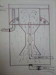
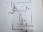
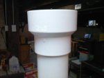
Water from the pond will gravity feed into the barrel chamber and rises up through a 2"-3" PVC tube to a level where the outlet of the tube meets a stilling "vat" or chamber that is open at the top - and bottom. The water does not overflow this stilling chamber, it slows in velocity and must redirect its flow to fall towards the bottom of the barrel, taking the heaviest sediments and debris with it. At the bottom of the barrel, the waterlogged and heavier sediments will collect and accumulate around the evacuation port (the drain) and can be exhausted when necessary by opening the valve.

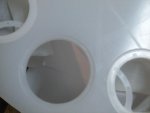
Cleaner water, or that water that has lost its "load" must eventually rise to the outlet port, however, on its way, it will meet a baffle plate which will be constructed with several circular holes. These holes will be screened off with 300 micron SS fitler panels. Once the water passes through and reaches the top level of the barrel, it may pass through a perforated PVC standpipe, wrapped with finer mesh, cleanable, nylon mesh fabric (maybe 100 microns). This mechanical filter as well as the SS panels will all be designed to be easily removed and washed clean at periodic intervals - but the main duty of this first stage barrel is to "drop the muck" before it even gets to these fitler screens.

The principle of operation is exactly what Paul van der Werf explains in his radial flow filter videos, so I am applying that principle to the overal function of this barrel filter, yet adding my own DIY components to make it fit my own ideas.

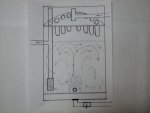
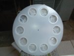
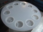
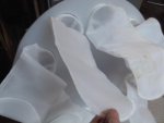
The outlet or effluent water from this barrel filter will feed into the second mechanical filtration stage (another 55 gallon barrel). In that stage, I will incorporate ten - 50 micron nylon mesh filter socks to finish the job of large solids removal. These filter socks will also be easily removed and cleaned with a garden hose.

If you can discern the filter operation through my verbal description and the drawing I attached, let me know if you think that this filter is a good design or not.

Thanks,

Catfishnut
 

Attachments

  • 1120130808.jpg
    1120130808.jpg
    35.6 KB · Views: 1,473
  • 1120130810.jpg
    1120130810.jpg
    31.9 KB · Views: 1,374
Joined
Oct 14, 2011
Messages
1,276
Reaction score
661
Location
Cedar Bluffs, Nebraska
1121131345.jpg1121131404.jpgHere is the second filtration stage: A mechanical "sock" filter unit.

Within a 55 gallon barrel, a circular disc of polyethylene (1/2" thick) will be mounted near the upper portion of the barrel. Around the outer perimeter of the disc I have used a hole saw to cut ten ~4.25" holes and used a rounter bit to recess the edges so that I may drop in ten, 100 micron, nylon sock filters. The effluent water from the "AXIAL FLOW SOLIDS SEPARATOR" will enter this barrel via a PVC pipe and dump onto the center of the polyethylene disc.

The water will be distributed / channelled to each of the sock filters with the addition of some plastic guideways set in sort of a star pattern (not shown in the diagram). This guideway will assure that the water is guided to all of the sock filters more equally if the entire disc is not perfectly leveled in the barrel. This is just going to be an added measure to ensure that I am taking full advantage of each sock filter and utilizing each to them as equally as possible.

The filtered water will flow down through the sock filters into the lower portion of the barrel where it will be allowed some settling time or possibly be aerated and heated if I desire to. It will then exit the barrel via a perforated PVC pipe to go on to the next stage (which will be a Kaldness K3 moving media bio-conversion unit).

Every 55 gallon barrel in the system will have a drain line, although it won't be necessary to purge every barrel for routine cleaning. In this stage, there shouldn't be much if any gunk or settlings in the bottom to purge out. That gunk should all be collected in the sock filters. But, it is always necessary to provide a drain to allow for any repairs or long term cleaning, etc.

Here is the attached drawing, you will notice how immensely simple this stage is. Not much to it at all.

Catfishnut
 
Joined
Oct 27, 2011
Messages
1,993
Reaction score
1,786
Location
BC Canada
Nobody seems to be responding Catfishnut,so for the sake of argument I will do my best to criticize of your design a bit and then you can respond. :beerchug:
The shape of the inner chamber of axial flow separator looks like it might be hard to make, unless you come across something that just happens to work. I've think a cone shaped tanks work much better for settling tank, much easier to drain out cleanly.
Why not just use a sieve instead of a settling tank?
I have a vortex settling tank, and I went that way rather then a sieve because it was safer for my fish and other critters because if they do go through the bottom drain they get trapped in the settling tank and I can spot them and remove them back to the main pond. It doesn't look like that would be possible with your design?
 

JohnHuff

I know nothing.
Joined
Apr 17, 2012
Messages
2,257
Reaction score
1,621
Location
At my computer
Hardiness Zone
1a
Country
Kyrgyzstan
Ya, I've looked at that design too from that website and don't know where the "radial" comes from, it's just a bucket and some pipes. This was a long time ago, but I did envision an improvement to it, and that was to add moving media to it so it would double as a bio filter. In your top picture, the media could be put in the top compartment.

To be honest, I think the best settlement chambers are the vortex filters where centripetal force would help the settling.
 
Joined
Oct 14, 2011
Messages
1,276
Reaction score
661
Location
Cedar Bluffs, Nebraska
Hi Randy,

Thanks for your critique!

Allow me to explain the shape of the inner settling chamber and why it will be easy to construct.

The inlet pipe will be 2" to 4" diameter PVC. The outer pipe surrounding the inlet tube, the settling chamber, will be 6" PVC (or maybe 8" diameter maximum) at the core. The top and bottom "flanges" will simply be PVC pipe adapter fittings that will enlarge the pipe from 6" to 8" (or maybe 8" to 12" diameter pipe at the maximum).

The adapters may be a bit on the expensive side, but I won't have to DIY fabricate them and I know I can buy them off the shelf at a local shop. Otherwise, the center, settling chamber could simply be just a 6" or 8" PVC pipe throughout the whole length. I just thought that the upper and lower "flanges" might aid in the settling process as it would allow more time for the water to slow down and add more retention time for the semi-waterlogged solids to precipitate out to the bottom.

In one of the videos I have reviewed from EarthanGroup with Paul Van der Werf, he presents using an inverted bucket or pail over the top of the inlet pipe. That is very simplistic and easily set up, but I thought that this was just as easy if not moreso - barring the cost of the PVC fittings.

My design concept here allows me to add a baffle plate around the outer diameter of the settling chamber easily. The baffle plate will allow me to incorporate the SS 300 micron filter screening into the design. The cleaner water which rises to the upper and outer area of the barrel - outside of the settling tube, will have to exit the lower portion of the barrel through the SS screening. This will allow further mechanical filtration of the solids which don't settle to the bottom.

The inner core or settling chamber and the baffle plate will not be attached to the barrel or the inner (inlet) PVC pipe at all. That whole assembly can be lifted out of the barrel whenever it is deemed that cleaning or maintenance is required. I will simply construct some sort of shelf or "rests" for the whole assembly to sit upon when installed in the barrel.

The outlet pipe will stick up through one port hole in the disc and it can simply be just a press in fitting (no threads and not glued). So I would just snatch it out first and then pull the settling assembly chamber out from the barrel, open the drain line and hose the bottom of the barrel out - exhausting the fish waste and uneaten food, etc. out to my trees in the yard for nutrients and irrigation.

To address your very last statement regarding fish or other small critters which might get sucked into the pond outlet and onto the filter... These small fry and whatnot can only make it into the bottom of this first stage filter - the axial flow sediment chamber. They cannot go any further than that as the exits from this tank will all be screened off to that size of fish. They would remain in the bottom of this first tank until I discover them there and remove them.

The only portion of the first stage that won't come out of the barrel will be the inlet piping. But, the settling chamber will simply slide into the barrel over the top of the inlet pipe and can be easily pulled out without any hardware being required to be removed or unfastened. In other words, it will just sit inside the barrel on a shelf or a few little blocks bolted to inside perimeter of the barrel. I can take the cover off the barrel and grab ahold of the assembly and lift it right out. Then, all I see inside is the inlet PVC pipe coming up through the center, the stand pipe for the outlet on one side of the barrel and the bottom of the barrel and the drain port.

Regarding using a sieve or sieve-type filter: I have contemplated this in the past and had a nice design drawn up, but I have presently opted against it for reasons of construction concerns.
After reviewing Paul Van der Werfs videos, I believe that I can get the job done without as much intricate fabrication and assembly efforts as I had originally planned. I also want the total system to operate with the least amount of human intervention for maintenance and to be the most maintenance friendly when maintenance is necessary.

Catfishnut
 
Joined
Oct 14, 2011
Messages
1,276
Reaction score
661
Location
Cedar Bluffs, Nebraska
JohnHuff said:
Ya, I've looked at that design too from that website and don't know where the "radial" comes from, it's just a bucket and some pipes. This was a long time ago, but I did envision an improvement to it, and that was to add moving media to it so it would double as a bio filter. In your top picture, the media could be put in the top compartment.

To be honest, I think the best settlement chambers are the vortex filters where centripetal force would help the settling.

John,

I originally thought that a vortex filter would also be the better choice, but I have since modified my opinion. I think it depends upon the size of the vessel and there is a dividing line or limit where one becomes more effecient or effective than the other. I am currently thinking that for a smaller vessel, the "axial flow" separator as I call it, will be better. Maybe I am wrong, but I am going to test this design out with my system first and see how well it works, then I can experiment later and swap it out with a vortex style tank of the identical size and compare the results. Right now, I have no data to make an educated conclusion upon. All I have to go on is what I have read from others.

You mentioned using this (my axial flow system) with a moving bed media - maybe like Kaldnes K3 or something... That's a possibility. However, Paul Van der Werf has the same concept in another one of his videos. He refers to it as a "swirl filter". I am thinking that this would not be a good application. The water entering this first vessel would be the most filthy and full of dissolved and undisolved solids which would probably not beneficial to the bacteria colonies residing upon the media.

My thoughts here are to let this first tank do its thing as "settling type" filter chamber and then further filter the escaping fines in the next chamber with the sock filters.... then direct that water into my moving bed Kaldnes K3 bio-conversion chamber. This would ensure that the influent water is free of most particulates over 100 microns and therefore not affect the bacteria cultures by coating them with such solids. Leaving chamber #1 the water would be filtered down to 300 microns and leaving chamber #2 the water would be filtered down to 100 microns.

Chamber #3 will have the responsibility of just doing the ammonia conversion to nitrites and nitrites to nitrates. Here, I will want some manner to circulate the media, like an aerator pad or a venturi. That will provide O2 as well as the circulation, besides just the water flow. I think that puttin this media in the first chamber, coupled with the turbulence necessary to churn the Kaldness media, woulod interfere with the settling process I want to achive in that first stage.

The next chamber, chamber #4, will be a showered Matala mat media. Maybe. Not that it would truly be required, but I have the media rolls and the barrel ready to install them in, so.... That is just my plan right now.

The next stage, #5, will be a zeolite media bed inside a pool (sand) filter housing to catch any ammonia that is missed by the bio-conversion tanks as well as help to remove other unwanted compounds that zeolite can or might do. Instead of filling the pool filter with sand, it will be filled with zeolite.

The next stage after that, stage #6, will be a BIRM filter media bed inside another pool (sand) filter to remove iron and manganese. This stage will probably only be used when the pond (tank) is initially filled. After then it will only be used when it is neccessary to add refill water from my well which has a high iron content. Normally this stage will just be bypassed. Instead of filling the pool filtker with sand, it will be filled with Clack Corp's BIRM media.

The next stage, stage #6 will be an activated carbon filter. This will serve to just polish the water before entry into the main pond (fish tank). I just made a canister to hold the activated carbon out of PVC and some fittings and screens that I dug up from work. I can get the carbon free from work and therefore it is just a consumable and disposable item. no cost to my operation so I might as well utilize it.

Catfishnut
 
Joined
Oct 27, 2011
Messages
1,993
Reaction score
1,786
Location
BC Canada
Catfishnut said:
John,

I originally thought that a vortex filter would also be the better choice, but I have since modified my opinion. I think it depends upon the size of the vessel and there is a dividing line or limit where one becomes more effecient or effective than the other. I am currently thinking that for a smaller vessel, the "axial flow" separator as I call it, will be better. Maybe I am wrong, but I am going to test this design out with my system first and see how well it works, then I can experiment later and swap it out with a vortex style tank of the identical size and compare the results. Right now, I have no data to make an educated conclusion upon. All I have to go on is what I have read from others.


Catfishnut
I'll be interested in seeing pictures and updates, and seeing the results. I have thought about modifying my current vortex tank to a radial flow system, but I'm not convinced the end results would really make that much difference.
.
Going back to critters and your design, you say "These small fry and whatnot can only make it into the bottom of this first stage filter - the axial flow sediment chamber. They cannot go any further than that as the exits from this tank will all be screened off to that size of fish. They would remain in the bottom of this first tank until I discover them there and remove them." this would be all well and good for fish to remain in the lower chamber, but frogs or turtles need to breath air regularly, and it doesn't look like they could have access to air down there. As I say, for a fish only pond, I guess this wouldn't be a problem.
 

koiguy1969

GIGGETY-GIGGETY!!
Joined
Dec 15, 2008
Messages
10,587
Reaction score
6,408
Location
Michigan zone 5b
On the second barrel with the filter socks... i would elbo the output pipe down to the bottom. the way it is once the barrel fills to the level that water will flow out the water will just flow right out leaving the water underneath doing nothing... being plumbed to the bottom the water will circulate thru. even fill it with bio media making it a down flow filter as well.
 

JohnHuff

I know nothing.
Joined
Apr 17, 2012
Messages
2,257
Reaction score
1,621
Location
At my computer
Hardiness Zone
1a
Country
Kyrgyzstan
Hi:
1) There is definitely an upper and lower limit in size. I know that because I always tried to make mini-versions of filters and found that at very small sizes, the polar properties of water affected the function of those devices.
2) I agree that adding moving media such as K2 to water with a lot of dirt in it would not be a good idea. But I was thinking of adding a perforated divider in the middle, such as in the following picture, and adding the K2 in the top divided chamber. 2 birds; 1 stone.
DIYfilter2.jpg

Edit: Thinking more about it, a divider of any sort, maybe a shaped divider or a divider with a shaped inlet would only help the settling. But I still like something with moving media best because it makes use of unused space.
Catfishnut said:
John,

I originally thought that a vortex filter would also be the better choice, but I have since modified my opinion. I think it depends upon the size of the vessel and there is a dividing line or limit where one becomes more effecient or effective than the other. I am currently thinking that for a smaller vessel, the "axial flow" separator as I call it, will be better. Maybe I am wrong, but I am going to test this design out with my system first and see how well it works, then I can experiment later and swap it out with a vortex style tank of the identical size and compare the results. Right now, I have no data to make an educated conclusion upon. All I have to go on is what I have read from others.

You mentioned using this (my axial flow system) with a moving bed media - maybe like Kaldnes K3 or something... That's a possibility. However, Paul Van der Werf has the same concept in another one of his videos. He refers to it as a "swirl filter". I am thinking that this would not be a good application. The water entering this first vessel would be the most filthy and full of dissolved and undisolved solids which would probably not beneficial to the bacteria colonies residing upon the media.
 
Joined
Oct 14, 2011
Messages
1,276
Reaction score
661
Location
Cedar Bluffs, Nebraska
Mucky,

I am hoping to assemble the first tank this spring. I won’t be ready to implement it in a full pond setting (my 1,000 gal tank) but I can set it up for experimentation. I can use a couple of 55 gal barrels to simulate a pond and then toss in handfuls of dirt or soggy fish food and see what it does.
As for the critters, I will be keeping only fish and possibly crawdads in the tank, but you are right that whatever happens to get into this first barrel would not be able to reach the surface of the water. However, I am going to use shower drains as the bottom drains in my fish tank. These will be covered with the metal strainers that they come with from Menards. The holes in the strainers are about 5/32” diameter, so they won’t allow anything very large to go down the drain.

KoiGuy,

Good idea to drop the effluent pipe down lower into the second barrel with the filter socks. I could install a Tee at the maximum level I want the water to reach in that barrel (just a few inches below the socks). I’d have the top of the Tee protrude up towards the top of the barrel to allow air in to avoid a siphon effect and the bottom could drop down low into the barrel. That way the water below the socks could circulate.

Dr. JohnHuff,

By replumbing the second barrel per KoiGuy’s suggestion, I could apply your suggestion and put the Kaldness K3 media in this second barrel with an aerator plate on the bottom to circulate and aerate the media and the water. Now there would be no unused space in this second barrel.
During the initial conditioning of the K3 media, since it likes to float high until colonized, I would only add so much media at first, then pull out one of the sock filters and add more K3 through the sock filter hole as the filter becomes established.
This also leaves the first barrel just for the settling of the muck. I can lift the center chamber out, drain the dirty water and hose out the bottom of the barrel periodically without affecting any other stage or disturbing any media.
This all should make these first two stages maintenance friendly and take full advantage of the available space.

Attached a revised drawing

Catfishnut
 

Attachments

  • 1124130513.jpg
    1124130513.jpg
    31 KB · Views: 513
Joined
Oct 14, 2011
Messages
1,276
Reaction score
661
Location
Cedar Bluffs, Nebraska
Here are a few pix of the polyethylene disc that I made to hold the sock filters and a pix of the sort of flange that I wish to use in the first barrel as part of the axial settling filteer (albeit much smaller than what I want for the end product).

Catfishnut
 

Attachments

  • 1124130556.jpg
    1124130556.jpg
    33.6 KB · Views: 409
  • 1124130557.jpg
    1124130557.jpg
    29.6 KB · Views: 411
  • 1124130600.jpg
    1124130600.jpg
    19.7 KB · Views: 388
  • 1124130602.jpg
    1124130602.jpg
    26.7 KB · Views: 398
  • 1124130604.jpg
    1124130604.jpg
    30.9 KB · Views: 408
Joined
Oct 14, 2011
Messages
1,276
Reaction score
661
Location
Cedar Bluffs, Nebraska
In step with the input from you guys so far, I have made the alterations mentioned previously PLUS, after spending just a few short hours of contemplating the design this morning, I have already come up with four more modifications (mostly details regarding orientation of the plumbing) which will make these two first stage tanks even that much more effective, maintenance friendly and easier to build. All of these are essential goals, so many thanks for your input thus far as it really helps guide my design process.

One change of noteworthy mention is this... Within the first tank, which I am calling the "AXIAL FLOW SEPARATOR", I am pondering making the upper portion of the flanged out area into somewhat of a vortex style mechanism. *Instead of leaving the inlet pipe open at the top of the vertical length, I ponder installing a Tee at the top of this vertical riser with two 90 degree ells attached to "swirl" the influent water around inside the upper portion of the stilling chamber before it flows downward.

i am not sure if that is going to provide me an advantage, but it is a design change that is very easily accommodated for experimentation and prototyping. Almost none of this is going to be "GLUED" together so I can just pull apart what doesn't function to my liking and change directions.

I'll leave you with those last thoughts and prepare myself to get some shut-eye time. (I work 4 pm to 4 am so I have only a few minutes left before I need to get to sleep).

Catfishnut
 
Joined
Oct 14, 2011
Messages
1,276
Reaction score
661
Location
Cedar Bluffs, Nebraska
I have been working on this design since we last spoke and have come up with what I really feel confident in.

I need to figure out how to get my pencil drawings of it converted to an image that I can share with you. I don't have a scanner so I will have to find someone who does.
The first tank, the "axial flow sedimenter" has been enlarged from a 55 gallon vessel to a 120 gallon vessel to accomodate a 12" x 12" square radial flow, mechanical filration screen (300 micron SS mesh) for starters.

So now this intitial or first tank will become an axial flow solids sedimenting and separating tank as well as a mechanical solids filtration tank.

The added square, 300 micron SS mesh filter unit is designed to be lifted up out of the tank and sprayed clean with a garden hose if and as necessary.
The frame will be constructed from 80/20 extruded aluminum (1"x1") sticks.

80/20 is a brand name for extruded aluminum products used in the industrial filed. Neat stuff! You should research it. We use it at work so I get scraps of it to take home from time to time for next to FREE. Otherwise, it is quite expensive.

My round tanks have "lips" or edges around the inner perimeter that I can set the 80/20 sticks on to support the structure from the top of the tank and I won't need to bolt it in place. This makes the item easily removable for periodic cleaning.

Just wanted to update you with my progress so far. Hopefully I can get pix of my new design to post for you to view in the near future. I will probably wait until I get most of my alterations drawn out before I do so that I don't have to do it twice or thrice, etc.

Catfish
 
Joined
Oct 14, 2011
Messages
1,276
Reaction score
661
Location
Cedar Bluffs, Nebraska
That is more difficult than it should be. Drawings in pencil don't show up with my cell phone camera. I drew the first pix in this thread with pen and had to go over the lines many times to make them dark enough to show up. I need to scan my drawings somehow. The lighting and camera exposure just are not good enough for my pencil drawings.

Will get it accomplished somehow, though.

Catfishnut
 

Ask a Question

Want to reply to this thread or ask your own question?

You'll need to choose a username for the site, which only take a couple of moments. After that, you can post your question and our members will help you out.

Ask a Question

Members online

Forum statistics

Threads
30,919
Messages
509,995
Members
13,127
Latest member
jcJohn

Latest Threads

Top